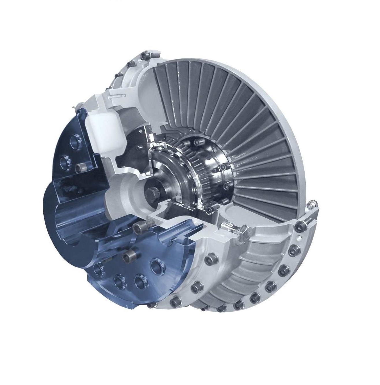
Hydrodynamic couplings

Hydrodynamic couplings belong to the group of hydrodynamic power transmission devices.
The power transmission is done by mass forces of the operation liquid according to the „Fröttinger Prinzip“. The impeller pump absorbs the mechanical power of the drive and increases the energy of the circulating operating liquid. The turbine wheel takes energy away from the operating liquid and outputs mechanical power. There is not any fixed connection between both wheels. Slight power losses, caused by the power transmission necessary slippage, will be transformed to heat.
The permissible ambient temperature range of the hydrodynamic coupling in standard design is between – 25 °C and + 40 °C (other values on request).

Hydrodynamic couplings are distinguished by:

-power transmission free of wear;

-steady shock free start up in loaded or unloaded state;

-slight backlash on the electrical power supply due to fast abating of the start up current and low start up current;

-load compensation on multi motor drives;

-efficient discoupling of vibration systems;

-damping of shocks, vibration and load changes;

-protection against thermical overload by the installed fusible plug or by a mechanical or electronical switch off device.

Types:

-type A: hydrodynamic coupling with delay chamber;

-type AV: hydrodynamic coupling with enlarged delay chamber;

-type AVZ: hydrodynamic coupling with an enlarged delay chamber and additional chamber;

-type AD: hydrodynamic coupling with two hydrodynamic units;

-type PO, P, PV, PVZ, PD: hydrodynamic couplings of the type AO, A, AV, AVZ, AD with brake drum according to DIN 15431;

-type SO, S, SV, SVZ, SD: hydrodynamic couplings of the type AO, A, AV, AVZ, AD with brake disk according to DIN 15432;

-type GMK: hydrodynamic coupling as before mentioned with two allsteel coupling halfes;

-type KO, K, KV, KVZ: hydrodynamic couplings of the type AO, A, AV, AVZ with pulley;

-type MEM: hydrodynamic coupling type (A/P/S)O, (A/P/S), (AV/PV/SV), (AVZ/PVZ/SVZ), (AD/PD/SD) for mounting the coupling to the motor shaft motor hub with threaded coupling connection and output side;

-type MRM: hydrodynamic coupling type (A/P/S)O, (A/P/S), (AV/PV/SV), (AVZ/PVZ/SVZ), (AD/PD/SD) for mounting the coupling to the motor shaft, clutch removable radially without moving the drive and driven unit, output-side connection coupling.

Categories: ,

Description

Technical characteristics.

Size range: from 274 to 1000.

Speed: from 1 200 to 3600 RPM.

Balance.
The couplings will be dynamically balanced. Standard balancing quality is Q 6,3 at 1500 rpm according to VDI 2060 in two planes.

Possible installation placements.
Hydrodynamic couplings can operate in both rotation directions and can be installed like follow described.
Mounting on the motor shaft / gearbox shaft:
The drive takes place on the outer wheel, which following advantages:
-the power transmission of the hydrodynamic coupling increased due to the fact optimized circuit;
-the hydrodynamic coupling can be thermally stability operate;
-the installed temperature monitoring system delivers always clear signals.

Typical applications:
-acclerating of large masses for example mills, centrifuges, mixer, blower, wood working machines, sieves, ball mills, rope machinery and tool machinery;
-start up against high break off torques for example mixer, conveyors, breakers, centrifuges and pumps;
-soft start up at tip and adjustment operation on large mobile equipment;
-safe overload protection for example at dredgers, breakers and scoop wheels.

Special designs for vertical installation of the hydrodynamic coupling are available.